Measurement & quotation preparation
Rubber Vibration Mount Thread & Dimension Guide
A mount can have the right rubber body size and still fail to fit if its threads or mounting lengths differ. Record the rubber dimensions and both connections separately before requesting a replacement or a quotation.
Use an approved drawing whenever available. Sample measurements help describe an existing part; they do not establish manufacturing tolerances or load capacity.
Send your drawing or dimensions1. Separate rubber height from overall height
| Dimension | What to record |
|---|---|
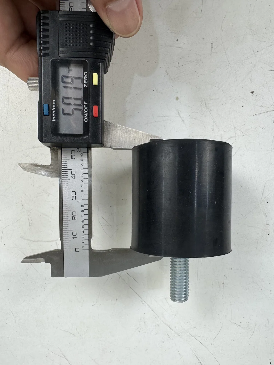
| Rubber body diameter or footprint | Measure the rubber body itself. Identify any metal plate, flange or shoulder that extends beyond it separately. |
| Rubber body height | Record the unloaded rubber height between its relevant end faces. Identify these faces on the drawing; exclude projecting studs. |
| Overall height | Label the two extreme reference faces used for the measurement, including projecting studs or metal features where applicable. Do not substitute overall height for rubber height. |
| Mounting-face spacing | Identify the faces that contact the equipment or base. Their spacing may differ from rubber height and overall height. |
| Installation clearance | Provide available space, mating-hole details and any nearby obstructions. Mark fit-critical dimensions and tolerances on the drawing. |
State the units throughout. Avoid an unlabeled “height” measurement: the rubber body, mounting-face spacing and complete assembly can have different heights.
2. Describe each end independently
Label the connections End A and End B on a side-view photograph or drawing. Our interface codes describe the connection arrangement: VE = male/plain, VV = male/male, DD = female/female, DE = female/plain and VD = male/female. They do not specify the thread size.
Male stud
- Record the complete thread designation from the drawing or confirmed part specification.
- For metric threads, specify nominal diameter and pitch. For inch threads, specify the thread series and threads per inch (TPI). Include a specified thread class when applicable.
- Measure exposed stud length from the identified mounting face to the stud end. Distinguish this from the stud’s complete length, which may include an embedded portion.
Female thread
- Confirm the thread designation and pitch or TPI using the specification or appropriate thread inspection tools.
- Record usable fully threaded depth separately from total hole or drilled depth. A depth reading alone does not identify how much of the hole has complete threads.
- Provide mating-fastener details and the required engagement and clearance for review against the drawing.
A caliper diameter reading alone does not establish a complete thread specification. Similar-looking metric and inch threads should not be treated as interchangeable. Use a suitable pitch gauge to check pitch, and confirm fit and any specified thread class with appropriate inspection tools.
For a blind female thread, check the specified usable depth and mating-fastener length before assembly. Do not force an uncertain thread fit; tightening torque must come from the agreed assembly specification.
3. Record the sample without deforming the rubber
- Measure the part unloaded. Note visible wear, deformation or damage that may affect the readings.
- Use clean measuring faces and light contact on the rubber. Avoid compressing it with the caliper jaws.
- Check more than one position where useful. Record the observed readings and measurement locations; do not turn their variation into a production tolerance.
- Take a side view and a clear photograph of each end. Label End A, End B and the reference faces for height and length.
- Add the mating-part drawing or photos, available installation space and any existing part markings. Mark unknown details as “to be confirmed.”
4. Copy this dimension checklist into your inquiry
Attach your drawing or sample photographs, then complete the fields you can confirm. Keep both end connections separate, even when they appear identical.
Rubber vibration mount – dimension checklist
Model / drawing number and revision:
Units:
Rubber body diameter or footprint:
Unloaded rubber body height:
Overall height and measurement reference faces:
End A – male / female / plain:
End A – thread designation, pitch or TPI, and specified thread class:
End A – exposed stud length or usable fully threaded depth:
End B – male / female / plain:
End B – thread designation, pitch or TPI, and specified thread class:
End B – exposed stud length or usable fully threaded depth:
Mating parts, clearance and critical tolerances:
Drawing / photos / physical sample available:
Application, material and hardness if specified:
Trial / production quantity:
Delivery destination:
Unknown details to be confirmed:
For equipment weight, support positions, operating conditions and the remaining purchase details, use the full rubber product RFQ guide and email template.
Open the mount inquiry formCommon measurement questions
Can you identify the thread from a photograph?
A photograph helps identify the connection arrangement and what needs checking. Confirm nominal diameter, pitch or TPI and any specified thread class from the drawing or suitable inspection tools before production.
Is rubber height the same as the installed height?
Not necessarily. State whether the measurement is unloaded or installed, and identify its reference faces. Compression under load and metal features can change the relationship between these dimensions.
Can a sample measurement define a replacement part?
It is a useful starting point. Review wear, original specifications, fit-critical tolerances, material, hardness and service conditions before agreeing the replacement drawing.
Continue your selection
Browse rubber vibration mounts → · Mount selection guide → · Prepare your RFQ →